PRR position light signal

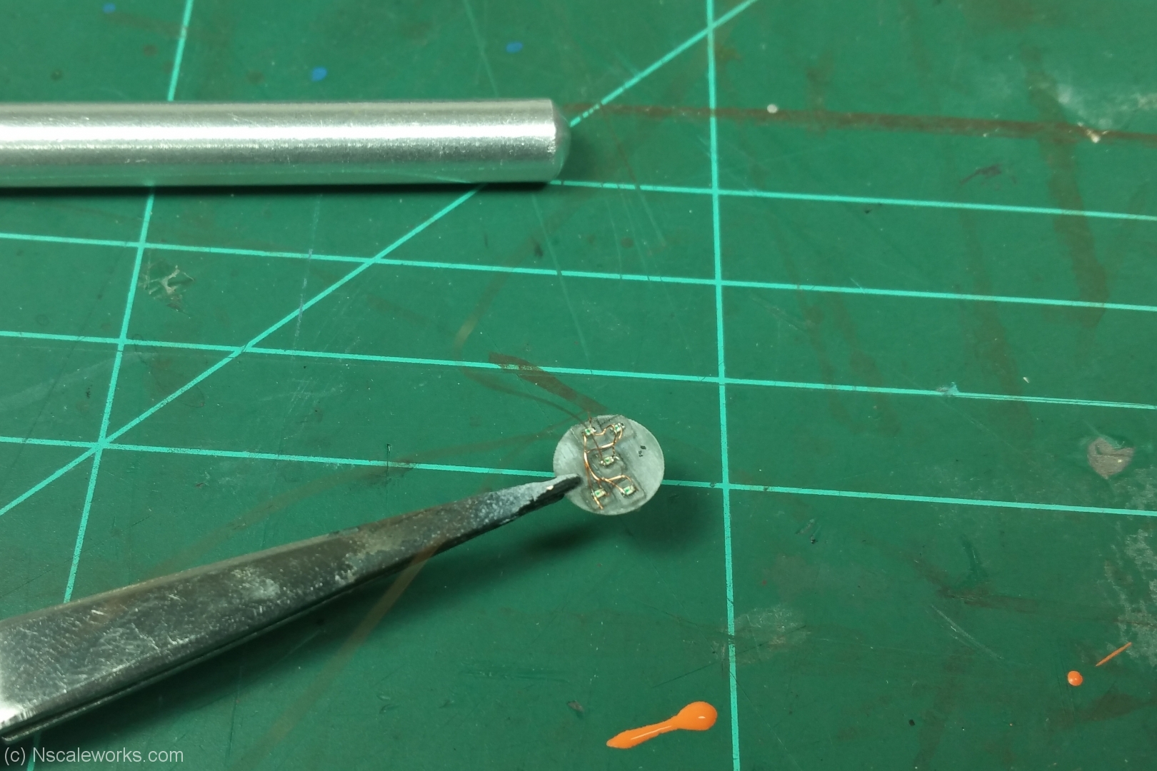
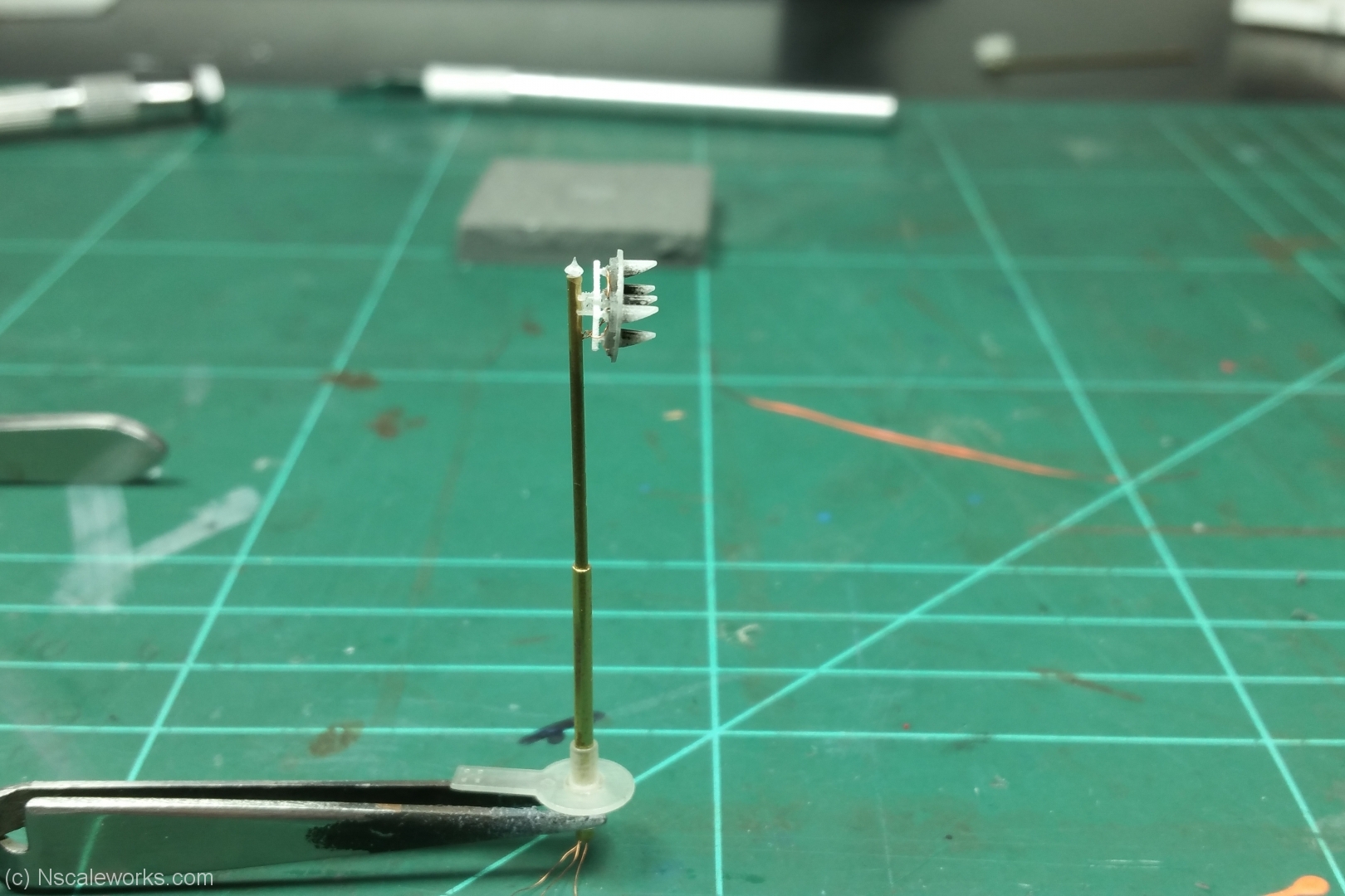
After some time spending on the “best-practice” for assembling the multi-parts head on the PL I came around with a good alteration of the prototype. Photo below shows the last testrun. Tiny SMD 0402 inserted into the lamp holes, and the head glued to the crossarm section.

prr_10

prr_12

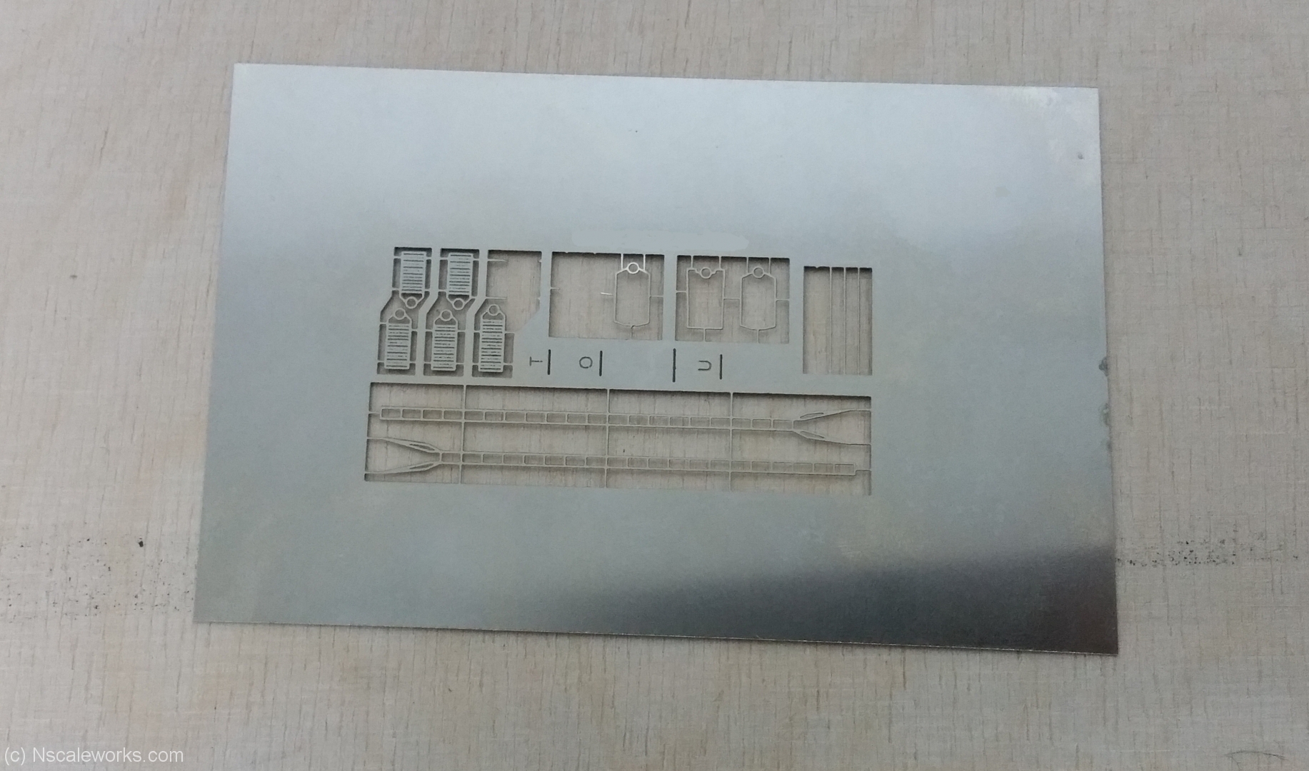
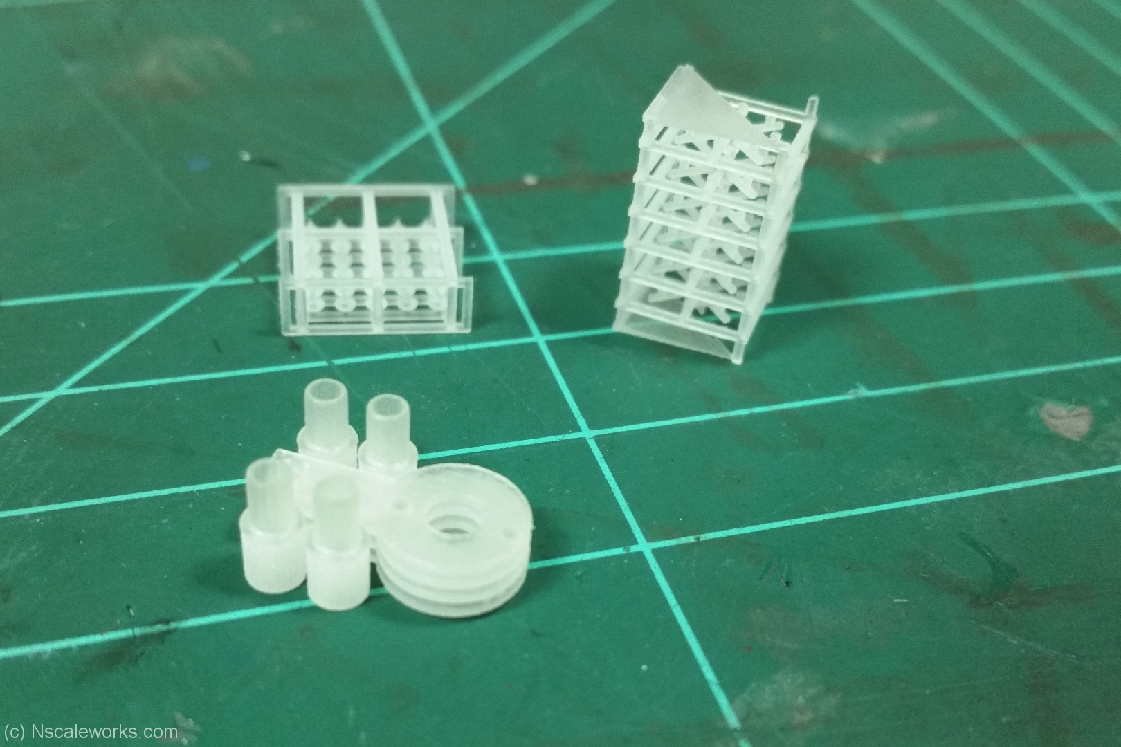
I also managed to get some more detail parts done, the 3D printed bae and some photo etched ladders and plattforms.

prr_13

prr_11

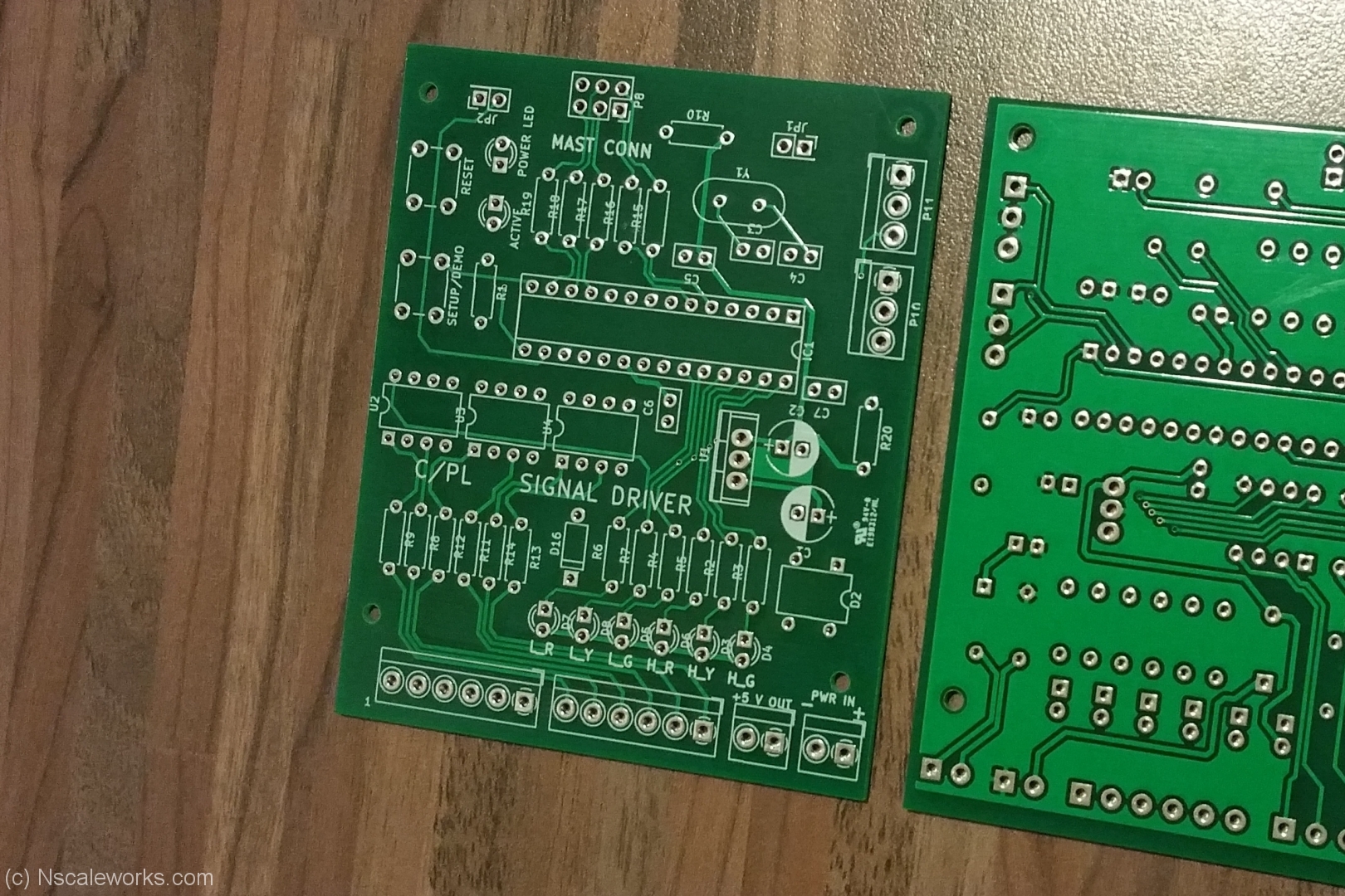
And last but not least, I manged to get the firmware running on the chip and with a littel help I manged to design a circuit board which will incorporate the mast socket and 6 input ports arcording to match the output on a SE8C from Digitrax Inc.

prr_14

PRR style signals

A working PRR style position light signal in N-Scale ?

My current effort is to make this model available at least for my C&E layout where I need want to install signal protection on two junctions.

At present I spent more than 150 hours of labor and research into this project, starting back in 2016 with an idea on charlieplexing 16 LEDs needed by a full aspect PL.

With this I could reduce the 16 x 2 wires to only 5 wires for the full mast.

Below are two sample vids

First test with 3 mm LED and individual control :

Second test with 0402 SMD in an scale signal head :

International Railroad Exhibition, Cologne – Germany 2016

I attendet our large railroad exhibition at Cologne from 11/17 to 11/20 along with the NMRA European Region A.s.b.l.

Beside some real good chat with visitors I was able to show some of my weathering work live at the show.

Here is a little pictoral of the event :

Our booth at the show. Besides my microlayout and workshop we had two more layouts on board. Alain Kap, MMR – “R.I.P. Car Shop” and Pit Karges – “First snow on the Highline”.

20161119_131002_small

My micro-layout more pictures can be found here.

20161119_084915_small

Some of my recent art?-work in a secured display.

20161119_084922_small

Done during Day #2 at the show. Arkansas & Missouri Boxcar after decent proto flick. On the right half of car #1

20161119_120311_small

I finished off three cars during the show.

20161120_162632_small

Thank you all who came for a visit to the booth

Downtown Spur

Perspective

My micro-layout “Downtown Spur” will be featured in October issue of MIBA Miniaturbahnen. I entered the layout and some flicks earlier this year.

I am very pleased to be recognized for the contest. There will be an public vote where – so it seems – every one can participate via a website MIBA will anounce later

If you are interested in all contestants please feel free to visit MIBA’s contest site. Downtown Spur is # 17

Link to MIBA contest

Weathering after prototype

Recently I finished a new weathering project after a protoype photo.

I had this PCA boxcar sitting on the layout for almost 2 years and came across a protophoto on RRpictrues.net showing a PCA box dating to my timeperiod around 1980. Perfect hit.

http://www.rrpicturearchives.net/showPicture.aspx?id=2833060

So here we start off: I need some additional decal to match the two parts COTS and Weight stencils. I also designed a yellow dot, which was used around late 1970 to mark cars with intakt wheels.

20160527_210320

Next step after appling the decals was to get a decent initial overall fade to the box.

20160601_215131

Followed by various layer of powderized pastels.

20160603_214243

And the finished version on an outside shot.

P1030746_res


A little engineering

while back I messed around with DCC decoder and their cables. Then I switched over and used drop in decoders.
Now I am on a turning point again, as I want to convert my entire fleet to DCC with sound. There are some drop in decoders on the market that are plug’n play sound decoders.
But what if you want to fit a wired DCC decoder in your engine ?
Ok, you have the decoder, but need some modification on the DC board, you need a place for the LED and speakers. Well, all floating around somewhere ?! … Big mess in little space !

So I sat on the design board and drew some PCB boards.
One kind of adapter which fit into the original split frame notches for power pickup and where you can solder the wire for motor power and front/rear headlight.
And a second board where you can place a SMD LED and resistor of your choice, simply hook up two cables and you have your LED light board.

20160409_135137_small

The PCB sitting on the split frame of a LifeLike GP18


20160411_212730_small

The test-lab on rails. Wired adapter board and both LED boards. I am using a stripped down Digtrax SDN136PS sound decoder for testing purpose. The wire for the rear LED board needs to be longer to get the board down to the frame.


20160411_212740_small

A close-up of the LED board and wired adapter.


20160411_212911_small

20160411_212924_small

Lights on, please !

Scroll to top